Emporia Energy Community › Share Your Emporia Experience › Install with flexible sensors, subpanels and a separate enclosure
- This topic has 5 replies, 3 voices, and was last updated 1 year, 6 months ago by
just1moredave.
-
AuthorPosts
-
-
just1moredave
MemberI just finished reinstalling my Vue Gen2 with 16 sensors. I borrowed a few ideas from here after not liking my first installation. Maybe this will help someone else get it right the first time.
My main panel is outdoors. It combines a meter enclosure and space for 20 breakers. Then I have a subpanel inside with another 20 breakers, and a subpanel in my garage. When installed, outside was all 240V circuits, inside all 120V circuits, but that changed a little when I got a heat pump and HP water heater. Because of the combined meter enclosure, I had to use the flexible current sensors. I planned to use 8 sensors outside and extend wires for 8 inside.
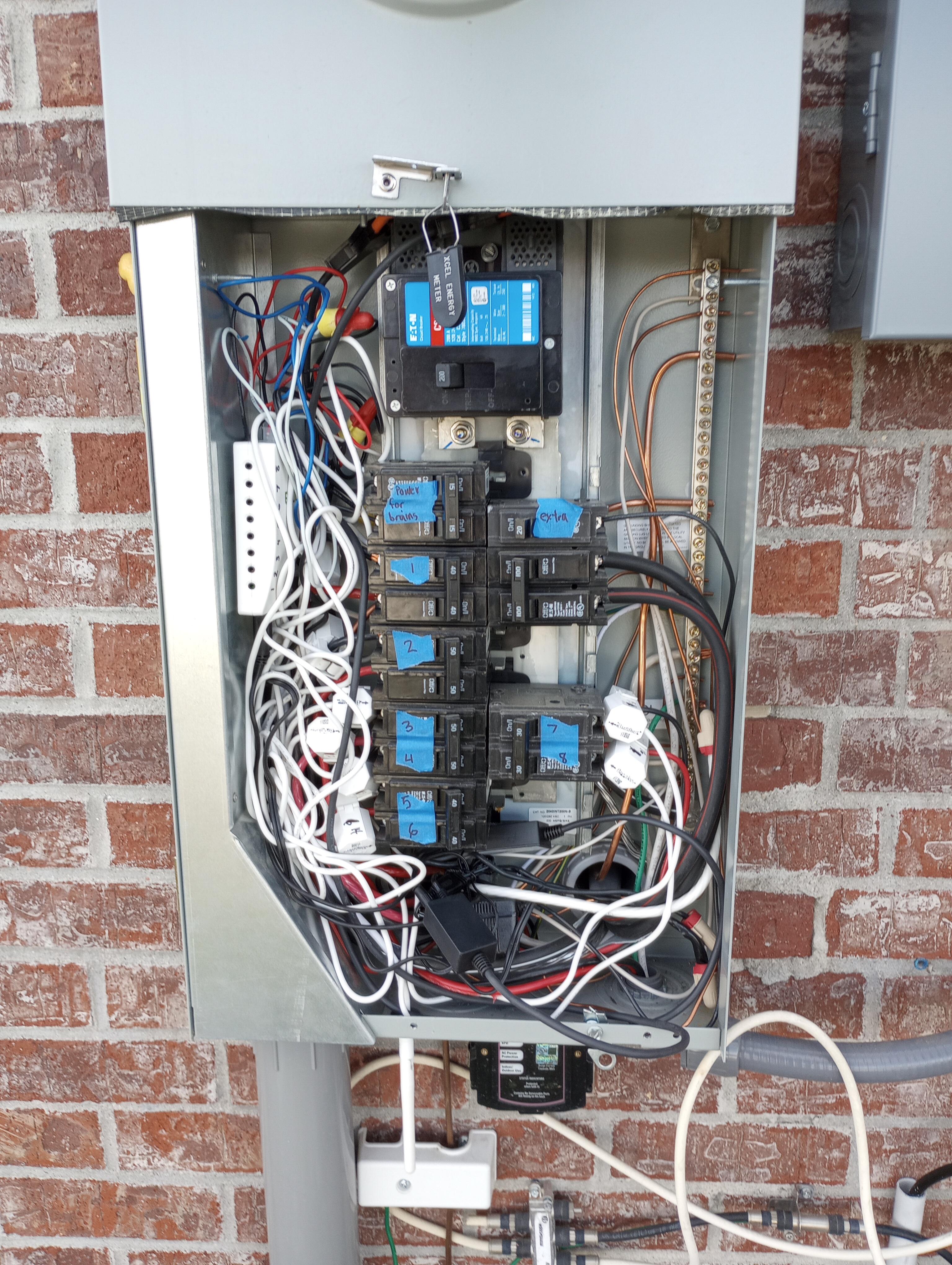
Here is the first try, just monitoring the outside panel with 8 sensors. It worked but was so jammed in the enclosure, I could barely get the covers back on.

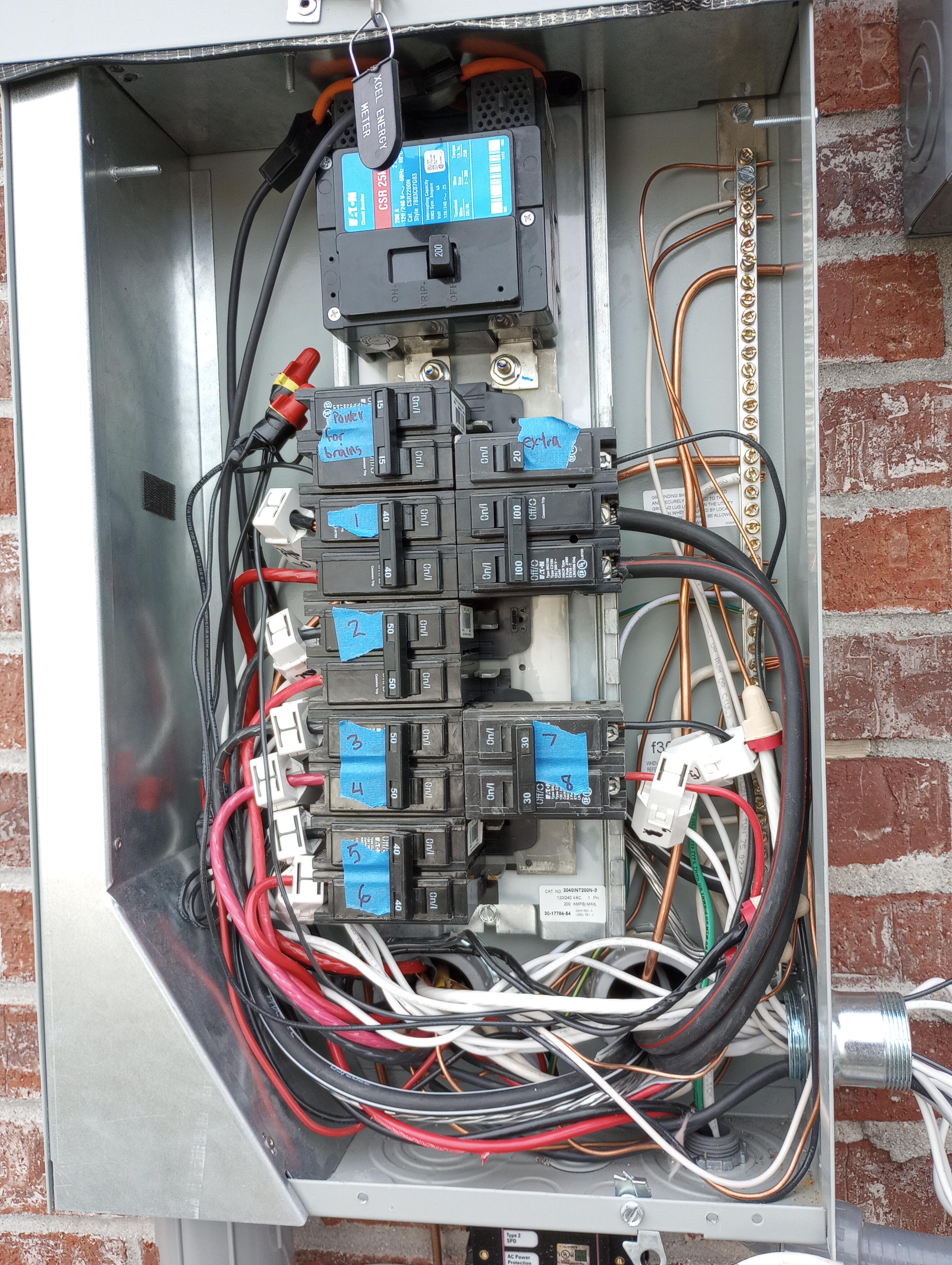
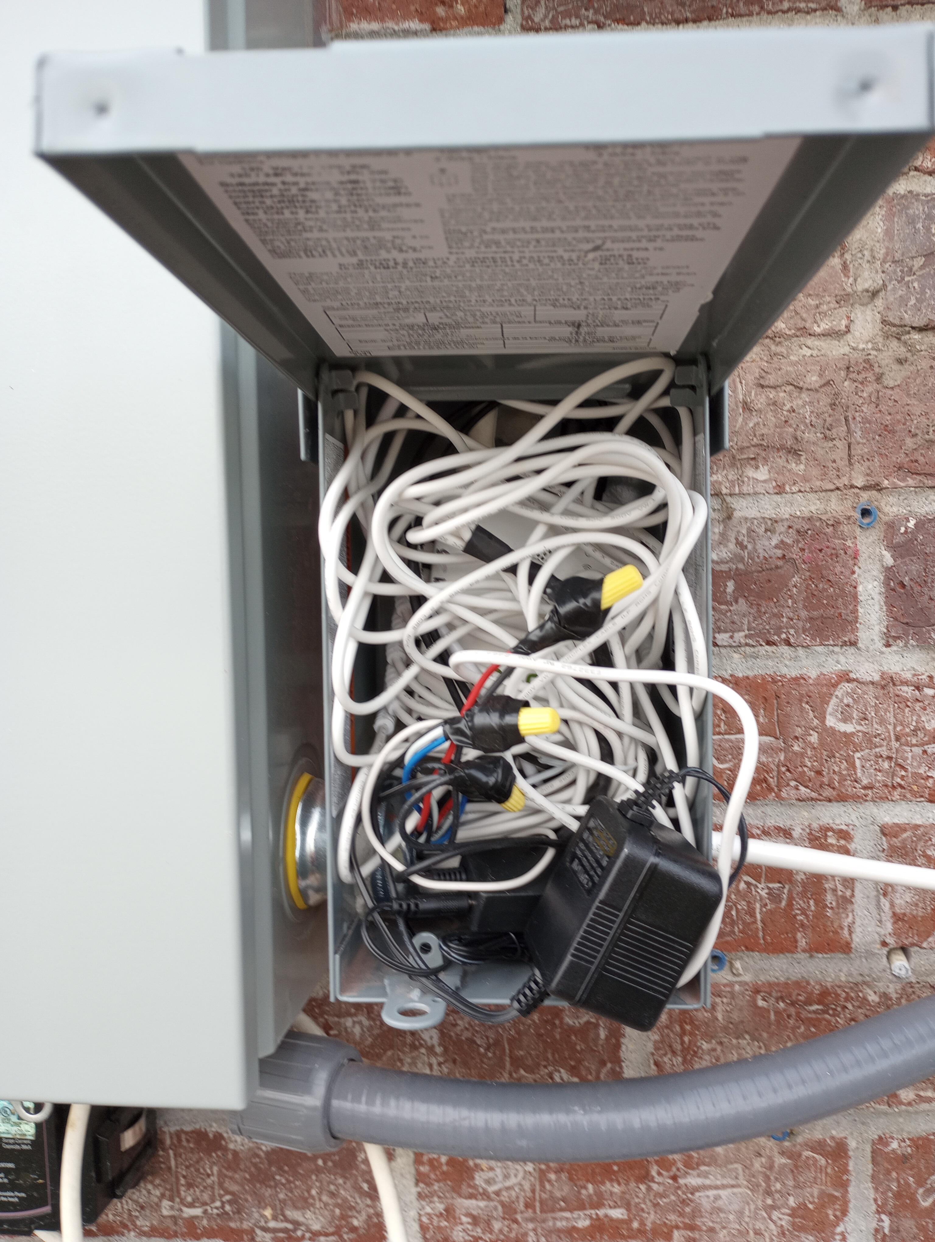
I needed to change something before adding the 8 inside sensors, but it was cold and I was out of patience. I saw photos in this forum using a separate enclosure, awesome idea. So here is the second installation on the main panel.

That’s a better view of the flexible current sensors. The sensors are small but they need extra space for a power supply and two “integrators”. Now I just have sensors in the main panel and run all the cables out a 1 1/4″ short EMT conduit on the bottom right. I think that diameter is important because it is big enough for the integrators to fit, as well as the right angle sensor plugs. You can’t see it well, but there’s a conduit out the back wall of this box leading to my inside panel. I used some CAT5 network wire to extend the 8 inside sensors, so I only had to fit two CAT5 cables through this hole.

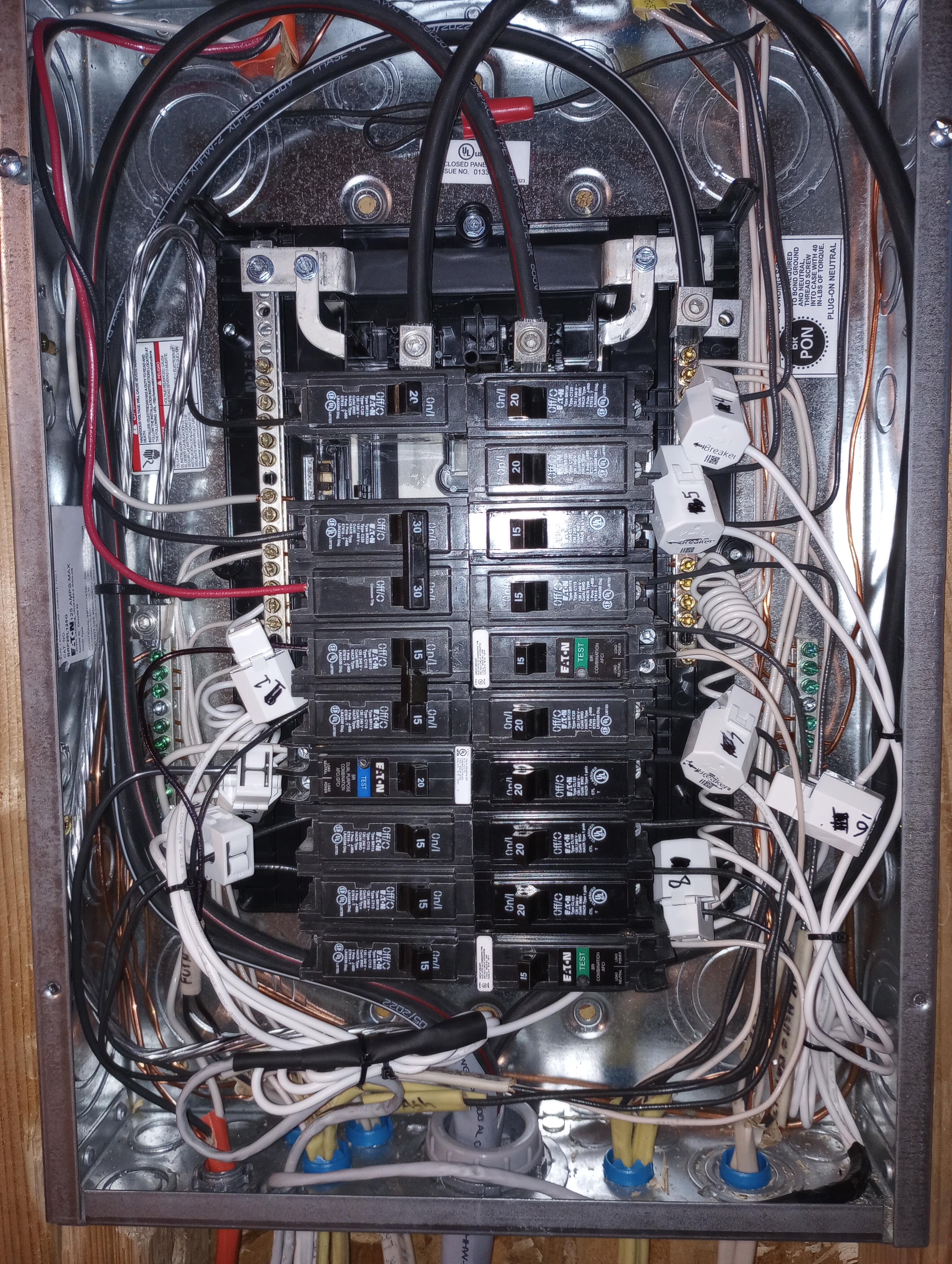
This Square D enclosure was outdoor rated, $39 and available at Home Depot. It’s still not quite big enough for neatness but it all fits. I ran out of zip ties. And to finish off, here’s the inside subpanel.

-
emporiacs
Emporia StaffThanks for sharing! Let us know if you have any questions.
-
kenz
MemberNice! Looks really neat. But I have a possibly dumb question as I just installed: the instructions said that the arrows on the CT were supposed to point to the load. This is a bit painful as it means the wires coming out of the CTs point towards the breaker, and make it messier. You have your wires from the CT going away from the breaker, but that makes the arrows on the CT clearly pointing towards the breaker (and thus away from the load). This is counter to the install instructions.
Any thoughts? Am I being too neurotic trying to follow that instruction to the letter? It seems like Emporia support thought it was a nice install, so clearly THEY didn’t see this as a problem.
-
kenz
MemberEdit: Oh, interesting. I zoom in on your images, and YOUR CTs clearly say “breaker” along with the arrow. That is not what mine look like, and my instructions were very explicit: the arrow points to load (and they did not have breaker printed on them). So you get your wires neatly pointed away from the breakers, and I am stuck with a jumbled mess. Emporia, any comments?
-
emporiacs
Emporia StaffHi, here’s some context that should help:
200A CTs are bi-directional and should be installed in the same orientation.
50A CTs are not bi-directional, so the orientation does not matter.
-
-
just1moredave
MemberI spent some time with a Sharpie highlighting all those arrows and labels before installation. The flexible sensors are black so I used a silver Sharpie. I also tried numbering the sensors and their plug ends. When everything is stuffed through the conduit, it would be hard to trace an individual sensor wire. I changed my mind about the numbering system and numbered everything twice – don’t do that.
I have two “backward” 50A sensors for the solar breakers and it does bother me a little. 🙂
Another tip: if you redo the installation like I did, and have solar, reset the energy monitor app. My data was very confusing until I did that. Turn off solar and make sure an appliance is on and drawing power. In the app, use the menu, go to Manage Devices, your monitor and circuits, scroll to the bottom of the list and choose Reset WiFi/Solar, then maybe put in your wifi password again, then choose the I Have Solar option. Then switch on solar. The instructions are in the Solar Supplement PDF.
-
-
AuthorPosts
- You must be logged in to reply to this topic.
