Emporia Energy Community › Support Center › Hardware and Installation › Do the CT clamps need to be close to the breakers and the main terminals?
- This topic has 2 replies, 3 voices, and was last updated 3 years, 2 months ago by
Chuck.
-
AuthorPosts
-
-
currentdraw
MemberI have half breakers everywhere, so it is very hard to fit the CT clamps next to each other. So I clamped some of them far from the breakers – that should be fine, correct?
I cannot clamp the mains close either; I wonder if it is important to be symmetric in any way or it is fine?
They main wires are a bit too long so they make a loop inside the panel.
-
sodamo
MemberWas hoping to see answer to this as I have similar situation with a couple of circuits.
-
Chuck
MemberMy experience has been you can clamp the sensor anywhere on the circuit, they do not need to be next to the breaker. My electrical panel is very tight, so 5 of my 10 circuits I am monitoring use sensors that are located up to a foot away from the breaker. Everything works fine.
Using an AC clamp meter I can take current measurements anywhere along a circuit and the amperage will always be the same. For example, for my A/C compressor I can measure the current draw next to the breaker and at the compressor itself (a distance of at least 50 ft) and the readings will be the same.
This would apply to your mains, as well. However, if you have solar and you install your sensors BETWEEN the solar breakers and the meter, you get a NET reading. If you install the sensors between the main breaker and your individual branch breakers (as I have) you get your total load and not NET.
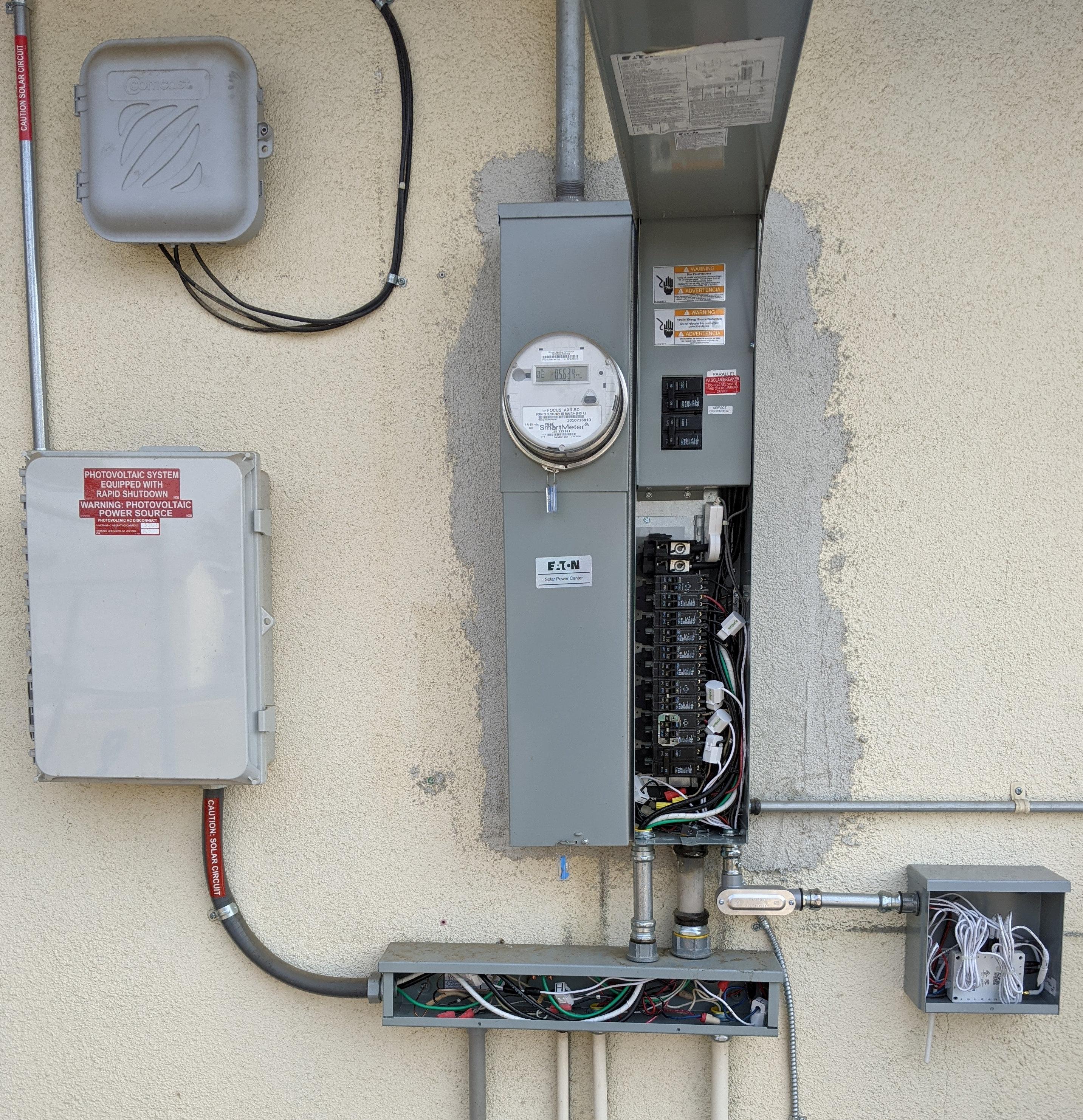
Attached is a picture of my install. You can see several sensors next to the breakers, but there are others located in the box below the main breaker panel that monitor several circuits, including my solar output. Also note that you can see only ONE main sensor in the picture (I use the optional spring clamps). The other sensor is located in the compartment just above the main panel, where the main breakers are. There was just not enough room to put both sensors in either place. Also note that because my panel is so tight I had an electrician install a nice little box that holds the Vue2 and the associated wiring. Without this external box there was no way I could fit the Vue2 in my panel. This setup seems to work fine.
-
-
AuthorPosts
- You must be logged in to reply to this topic.