Emporia Energy Community › Support Center › Hardware and Installation › Gen2 and (2) 200 Amp panels › Reply To: Gen2 and (2) 200 Amp panels
While we wait for the Emporia data services to be improved to be able to combine multiple Vues into one logical presentation in the app, here’s a couple solutions. And if you don’t need more than 16 branch circuits of monitoring for the entire home, then one Vue would always be better than two in my opinion.
I’ve learned from Emporia that the Vue understands current sensor signals equal to 370 amps max, and that is a lot for even a 400 amp service so a single Vue can reasonably handle a 400 amp service.
If the wires feeding the separate 200a main breakers are right next to each other at some point and accessible, you can put a single CT (current transformer aka current sensor) around both wires of each of the hot legs, one CT on two L1 wires and ditto for L2). The standard CT is probably too small in diameter but the rope CT should be big enough.
BUT, if the two wires are not accessible where close together (like behind the meter) or the two together are too big for the CT hole, then the other solution is to wire two CTs in series with only one jack on the end. Here’s the steps to do that:
Get 4 CTs that will fit around your main conductors. (You can order an extra pair on the website, rope CTs are larger in diameter and smaller in profile and easier to get into tight spaces.)
Take 2 of the CTs
On CT1, you cut off the last couple inches and the jack.
On CT2, you remove a couple inches of the outer insulation a few inches away from the jack. (If your arrangement warrants making the connection more than a few inches from the jack, that is perfectly fine. For example, you are placing the Vue in one panel at the bottom a couple feet away from the main conductors.)
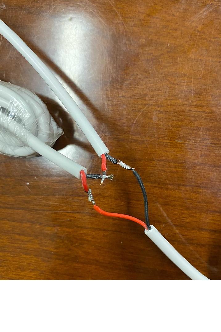
On CT2, you leave the red wire untouched but you cut the black wire and solder or wire nut it to the red wire of CT1.
Lastly you have two black wires unconnected so you solder or wire nut them together.
If you soldered, then heat shrink tubing covers your work nicely. Make sure that uninsulated soldered joints can’t touch each other, of course.
Now you have two main CTs, wired in series into one jack which plugs into the Vue’s A or B port like normal. And about seven feet or cable in between them. If you need a bit more (I have no idea how long before it becomes inaccurate), you could wire in an additional length of suitable two conductor wire.
Repeat the above with the other pair of CTs.
See the pic below (but don’t cut the red wire and have to resolder it too! 😉
I’ve also done this with two of the standard 3.5mm audio splitter adapters that I found at Walmart for $4 each. It’s no easier to modify t these into series, but it does leave the Vue CTs unaltered and seems more cool. This is the kind of product that a manufacturer could offer. The Vue jacks are TS (Tip, Sleeve) style and these splitters are TRS (Tip, Ring, Sleeve for stereo) style but it worked fine for me.
Remember that the pair of series CTs are placed on the same phase (one set is on the two wires of L1 and another series set on the two L2 wires). If one in the series is on one phase, and the other is on the other, they cancel each other out and yield inaccurate readings.
Hope this helps!