Emporia Energy Community › Support Center › Hardware and Installation › Gen2 and (2) 200 Amp panels
- This topic has 27 replies, 11 voices, and was last updated 1 year, 3 months ago by
jesse.
-
AuthorPosts
-
-
docderwood
MemberDoes the Gen 2 offer integration of two separate 200A panels for those of us with 400 Amp service?
-
Marty @Emporia
Emporia StaffHi @docderwood we are working on the ability to aggregate and combine multiple Vue’s into one load reading. We hope to have this available within the next couple of months.
-
BAT88
MemberI also have (2) 200 A panels–adjacent to one another. As we wait for this aggregate usage feature is the best hardware plan to install an Emporia Gen 2 in each panel? I have 10 or so circuits I would like to monitor in each.
-
OneMan
MemberWhile we wait for the Emporia data services to be improved to be able to combine multiple Vues into one logical presentation in the app, here’s a couple solutions. And if you don’t need more than 16 branch circuits of monitoring for the entire home, then one Vue would always be better than two in my opinion.
I’ve learned from Emporia that the Vue understands current sensor signals equal to 370 amps max, and that is a lot for even a 400 amp service so a single Vue can reasonably handle a 400 amp service.
If the wires feeding the separate 200a main breakers are right next to each other at some point and accessible, you can put a single CT (current transformer aka current sensor) around both wires of each of the hot legs, one CT on two L1 wires and ditto for L2). The standard CT is probably too small in diameter but the rope CT should be big enough.
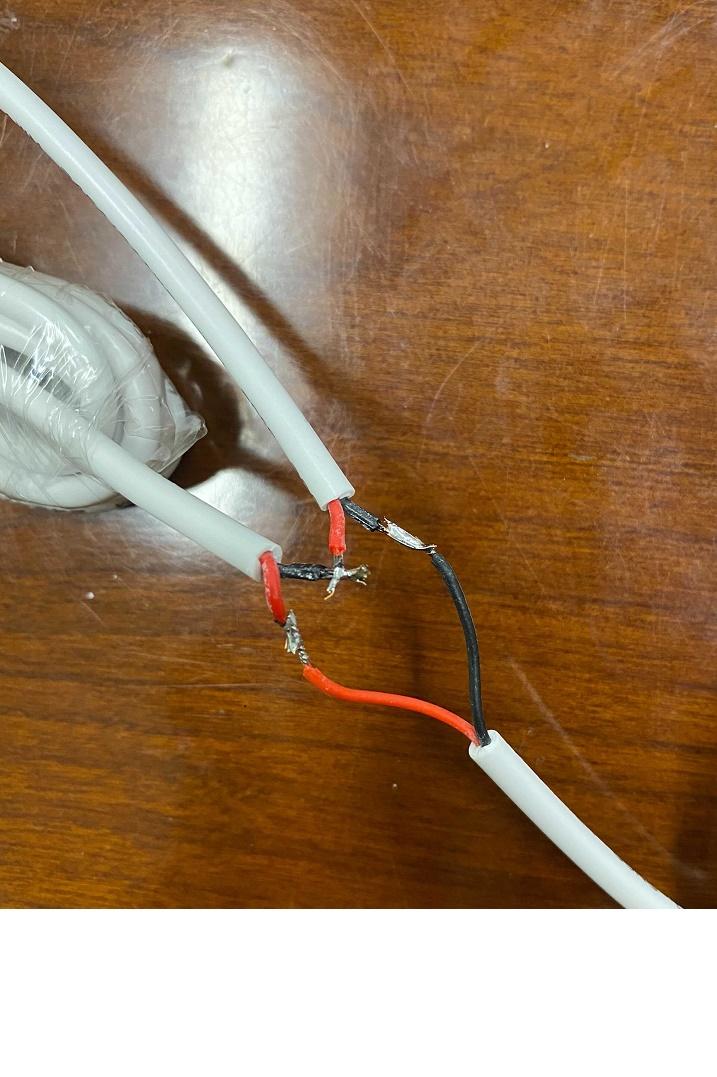
BUT, if the two wires are not accessible where close together (like behind the meter) or the two together are too big for the CT hole, then the other solution is to wire two CTs in series with only one jack on the end. Here’s the steps to do that:
Get 4 CTs that will fit around your main conductors. (You can order an extra pair on the website, rope CTs are larger in diameter and smaller in profile and easier to get into tight spaces.)
Take 2 of the CTs
On CT1, you cut off the last couple inches and the jack.
On CT2, you remove a couple inches of the outer insulation a few inches away from the jack. (If your arrangement warrants making the connection more than a few inches from the jack, that is perfectly fine. For example, you are placing the Vue in one panel at the bottom a couple feet away from the main conductors.)
On CT2, you leave the red wire untouched but you cut the black wire and solder or wire nut it to the red wire of CT1.
Lastly you have two black wires unconnected so you solder or wire nut them together.
If you soldered, then heat shrink tubing covers your work nicely. Make sure that uninsulated soldered joints can’t touch each other, of course.
Now you have two main CTs, wired in series into one jack which plugs into the Vue’s A or B port like normal. And about seven feet or cable in between them. If you need a bit more (I have no idea how long before it becomes inaccurate), you could wire in an additional length of suitable two conductor wire.
Repeat the above with the other pair of CTs.
See the pic below (but don’t cut the red wire and have to resolder it too! 😉
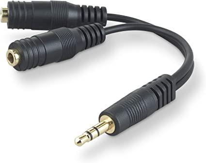
I’ve also done this with two of the standard 3.5mm audio splitter adapters that I found at Walmart for $4 each. It’s no easier to modify t these into series, but it does leave the Vue CTs unaltered and seems more cool. This is the kind of product that a manufacturer could offer. The Vue jacks are TS (Tip, Sleeve) style and these splitters are TRS (Tip, Ring, Sleeve for stereo) style but it worked fine for me.
Remember that the pair of series CTs are placed on the same phase (one set is on the two wires of L1 and another series set on the two L2 wires). If one in the series is on one phase, and the other is on the other, they cancel each other out and yield inaccurate readings.
Hope this helps!
-
rcohen
MemberCan this method of wiring in series work with opposite phase circuits if the clamp is reversed or if the leads on one of the clamps is reversed?
It would be great to be able to use this technique to combine unbalanced 220v circuits into a single circuit on the Vue, since I am out of jacks.
-
-
theProcessor06
MemberDo you know if this would work for combining total energy usage on two circuits of a sub panel?
Until we can combine, I have “SubPanel A” and “SubPanel B” since they recommend NOT using the multiplier and single sensor for sub panels. I’d love to just see the total use instead of having it broke out into A/B circuits. Would be great to know if anyone else has done this before I cut some of my 50A sensors.
-
This reply was modified 2 years, 11 months ago by
theProcessor06.
-
This reply was modified 2 years, 11 months ago by
-
Member
Yes, you can put multiple CTs in series in order to sum up the same phase whether it be the wires feeding a panel, subpanel, branch circuit, etc. 50 amp sensors, 200 amp sensors, rope sensors – doesn’t matter.
A caveat is that a distance of let’s say more than 10 feet between the Vue and one or more of the CTs may give a lower reading due to the resistance in the CT wires. I suppose the Vue Multiplier feature could be used to adjust for this.
And sometimes (rarely) the two subpanels feeder wires are close together or can be moved a bit to be right next to each other at some point in the run and you can route both L1 wires (hot legs 1) through one CT and you don’t need to series multiple CTs together. This applies again to any size wires that will fit through the CTs.
And the CTs handle a lot more than the 50a and 200a stated current. Can’t remember what it is exactly but it’s at least 50% higher than the stated amps.
-
brm252
MemberIs the feature to combine two units as one still in progress? I don’t see the ability to combine them in the app.
-
hammer
MemberHi, thanks for the suggestion to wire the CT’s in series. As an alternative, is it possible to use an additional 200a CT’s and plug it into the regular (1 – 16) inputs? I know the software won’t know to aggregate each breaker CT under the correct 200a CT, but this way, I can still monitor total usage of both panels. Will this work? Or just plug all four 200a CT’s into the 1-16 jacks so they are all represented the same in software.
Also, I see there is also a 3 phase Vue 2 unit available. That will come with 3 200a CT’s. Can I use a fourth 200a CT and plug that into one of the regular jacks to monitor my fourth line? I don’t know if the 3 phase Vue is set to 208V or not which is typical 3 phase service. My service is 120/240. Thank you.
-
Member
The mains current sensor (CT) jack is bigger (3.5 mm) than the branch circuit ones (2.5 mm) so NO on that one.
Regarding using 200a sensors for the other breaker panel but plugging them into a branch circuit, assuming you changed the plug end to 2.5 mm size, this won’t give you the result you want either because the Vue assumes the branch circuits are just that – a subset of the mains. So your panel A mains sensors would report x draw overall to the Vue and your panel B “fake” mains sensors with soldered 2.5 mm plugs on them and plugged into a branch jack would be subtracted from the panel A mains. The Vue would be worthless.
Regarding the 3 phase Vue, same situation – you can’t input mains current data into a branch circuit. You’d also likely have trouble with the voltage measurement if it is like the split phase Vue which only monitors the voltage on one leg and assumes the voltage of the other leg/s.
How far apart are your two breaker panels?
-
Member
Regarding multiple wires in one sensor and unbalanced, you can put multiple wires through any of the sensors as long as they are the same phase meaning that all/both wires are connected to Line 1 (L1) or all/both to Line 2 (L2). And of course, the Line and Load for all wires must be on the same side meaning that the current is flowing the same direction in all the wires and also flowing the direction of the arrow on the sensor.
I was short a Vue input so I combined my clothes washer and electric dryer onto one sensor I called “Laundry”. And the dryer is unbalanced meaning that it because the heating element is on L1 and L2 and the motor that blows and tumbles is only on one leg (almost all North American electric dryers are like this). So using my ammeter, I measured what the other leg/line was using and hand-calculated what the multiplier would need to be to get total usage and put that multiplier in that circuit’s screen in the app. Not a perfect measurement but I’m satisfied with it.
I didn’t quite follow your question about what sounded like reversing/flipping the sensor or reversing the jack plug (cutting and reversing the wires and resoldering the wires?).
Does that help?
-
Member
Thanks for the explanation.
I saw someone claim that you could mix the phase if you reverse the direction of the wire through the Vue, but perhaps that’s not true.
Did you find a good splitter to rewire instead of modifying the Vue cables? That would be nice, since I’ve been fiddling with my setup a lot, trying to track down issues. It seems like a lot of audio gear uses really tiny wires that are hard to work on.
-
Member
@rcohen, yes I tried an audio splitter like this but learned they are parallel not series, so it didn’t work. This splitter maybe could be cut and soldered and turned into a series splitter, but simpler I think to just do it with 2 CTs. I have been hoping that Emporia would offer a series splitter while we await the feature spoken about over two years ago that they were going to support 2 or more Vues summarized as 1 in the app.
I’ve never tried an L2 backwards in the same CT with an L1 forwards but …
-
yyzguy
MemberI’ve got parts on order to make a serial connection for the 50A CTs
It should be pretty simple to cut off the 90 degree 2.5mm TS and connect it two of the female jacks. That would make it possible to use two CTs in series connected to a single Vue input. I’m expecting to flip one of the CTs to get the desired results.
if it works, this method would likely be better than if Emporia mathematically merges two inputs because only one channel would be consumed on the Vue.
I’m assuming the “tip” is the signal and sleeve is ground. I’ll check that before wiring.
I just now noticed one of the parts is the wrong size so I’ll have to get an adapter or order the correct part, but I think the method should work
-
Member
According to Emporia support, it’s possible to connect the 50A CT’s to the 1-16 ports with a 3.5 to 2.5 mm adapter and adjusting the multiplier to 4. My plan is to not use the A, B, C ports at all and just monitor the mains and other loads independently. For total usage, I can refer to the Mains and for individual loads, I can use the load CT’s. Any issues with this setup?
-
Member
@yyzguy, could you post links to those? Let us know how it works out! If you get the polarity backwards, I think you would be able to reverse the direction of the clamps. I’m not sure how else to tell aside from taking an Emporia cable apart. Maybe @OneMan can tell us, since he has already done that.
-
Member
@rcohen, regarding having to reverse/flip one of the two CTs wired in series, both monitoring the same leg (L1 or L2), I don’t recall having to do that.
@yyzguy, I didn’t buy any parts other than an extra pair of 200a mains CTs from Emporia. Two CTs connected to one 3.5 mm plug for L1 and ditto for L2. When I was done, the waste was a pair of 3.5 mm plugs (male).
If the standard length of the CT wires/leads hadn’t been long enough for my application, I would have had to solder in some 2 conductor wire to extend them.
-
Member
@oneman I understand you didn’t buy any extra parts. My concern is I didn’t want to modify the CTs. I’m going to make my own series connector from parts.
I was editing on a tablet and found it simpler to post pictures rather than links to the products.
For the female part, I ordered from Amazon https://www.amazon.com/dp/B09V16N8NV. There’s nothing special about this part…it’s a 2.5mm TS (Tip/Sleeve). There’s many manufacturers of those. TRS may work
For the mail part, I made a mistake and accidently ordered 3.5 mm part which won’t work. It was quite a challenge to find a 2.5mm part with a right angle and just 2 conductors (three and 4 conductors are common place because they’re often used for stereo earbuds/headphone or single earphone plus microphone or stereo plus microphone). If you don’t require the right angle (which is what the CTs have) straight versions are easy to find. I don’t have enough physical space in my panel for straight connectors.
Anyway, I have since found two different sources
https://www.ebay.com/itm/274597758848 (I bought 4 and there was a significant discount. Total price was $17.28 plus shipping). I only need 3, but I figured a spare was worth having.
https://vetco.net/products/6-2-5mm-male-mono-pigtail-cable-right-angle I also found this source but had already ordered from the ebay seller before this seller was able to confirm they had inventory. (He has 35 in stock as of this morning)
Additional comments:
I had an email conversation with support and they said they’d see if they could “bump” the request to merge two channels with the developers.
If combining CTs in series works, I think it’s still a better solution because it would use a single port instead of two.
-
Member
@yyzguy, nothing wrong with making your own series “joiner” (a word I use to distinguish from the parallel splitter). Especially good not to cut the sensor’s wire in the case that it was faulty and you tried to return it to Emporia!
One question – you’re buying 2.5 mm parts? So you’re making a series joiner for 50 amp branch circuit current sensors? The 200 amp sensors have 3.5 mm plugs.
When you’re soldering your Amazon parts together, just verify that the sleeve section for both the male and female is connected to the same color wire and do the series join like my first post shows. Heat shrink tubing over the spliced wires is a nice touch. Look forward to seeing a pic. Going to be others who want 2 and even 3 CT series joiners too.
-
Member
Yes, I’m doing this to combine unbalanced loads into a single measurement. So, yeah…off topic from the original post, but related in the sense of trying to measure unbalanced 2 phase circuits. I had been working with tech support about measuring unbalanced load (clothes dryer) and I think they pointed me to your post about connecting two CTs in series. I didn’t realize the topic was initially about combining Vues. Somewhere there was also a mention about a software update to combine two sensors into one reading, possibly on a different thread. Sorry for the confusion.
-
Member
@yyzguy, an electric dryer’s L1 and L2 is for sure unbalanced (unequal current) because of the motor being only on one leg. But if you have two CTs, one measuring L1 and the other on L2, and you wire the two in series, each being a half cycle/Hertz out of sync with each other, won’t that give an erroneous reading? I’m thinking it would be positive current and simultaneous negative current which would cancel each other out and ONLY show any current out of balance. @rcohen has mentioned running the other leg through the CT backwards which wow – could that cancel the cancel? Love to hear what you two learn.
-
Member
Indeed if the CTs are wired in series with one measuring L1 and the other measuring L2 and they are 180 out of phase, that would be the equivalent of the difference between L1 and L2. Mathematically it would be L1-L2 (or L2-L1). However, if I flip one of the CTs (L2 for example), I think that would be additive. Mathematically it would be L1+L2. If I flip the wrong one it would be appear as -L1-L2 which would be the same value, but show as power being generated vs consumed. So yes, the idea is to cancel the cancel! If I understand correctly, flipping a CT would be the same as running the wire backward through the CT.
Then again, I could be wrong. That’s why I’ve ordered parts to create the series connection vs modifying the wires of two CTs. If I was confident this would work, I’d probably have already done the damage 🙂
And just to be clear: I inadvertently hijacked a conversation about combining two Vues or two panels. I came into the conversation in the middle, thinking it was about combining to sensors within a panel. I should have started a new conversation.
-
Member
@yyzguy, while we are just chatting away about this, one of the things that Jason Binder with Emporia learned (or already knew and showed me) while helping me experiment with multiple CTs is that if the CTs are in parallel (and all on the same phase/line leg), the reading is the AVERAGE of the CTs. CT1 = 12 amps and CT2 = 6 amps = 9 amps to the Vue2.
-
Member
What would be the reason to connect multiple CTs in parallel and connect them to the same line? I saw your earlier post about using an audio splitter, but I thought that was a mistaken attempt to connect two CTs in series.
-
Member
Parallel was the first test because it was easy with the off-the-shelf splitter. And with my solar system backfeeding the grid while I was doing these two CT experiments, the measurements I was seeing were hard to understand until Jason told me it was the average of the two and then it made sense.
Parallel gives the average.
Series gives the sum.
I don’t know if CTs in parallel has any practical application but just documenting it here for all those reading and researching.
-
Member
An average might actually be useful. You could combine an off-the shelf splitter with a 2x multiplier. No mods required.
With the out of phase thing running opposite, I just read it online somewhere. I’ve also read people saying that out of phase requires separate inputs. No idea who is right.
-
Bottoz
MemberAny official update from Emporia regarding this?
I also have 2 200A panels with a 400A main service.I have a Gen 2 Vue I haven’t opened yet, and an old Gen 1 from a previous house.
-
jesse
Memberif you can run the 200a sensors out through the wall into the meter box so you can clamp around the 400a lines before they split, maybe do that. i have dual 200a panels as well, and i think the highest combined load i’ve ever seen us use is about 60 or 70 amps when the hot tub is heating and all the minisplits are cranking out the cold air. unfortunately i can’t easily get into my meter panel without phoning up the utility to take off their tampering tag, so i’m just monitoring them separately
-
-
AuthorPosts
- You must be logged in to reply to this topic.