Emporia Energy Community › Support Center › Hardware and Installation › Can I monitor mains power by summing circuits?
- This topic has 3 replies, 3 voices, and was last updated 10 months ago by
emporiacs.
-
AuthorPosts
-
-
billmi
MemberI’m planning a Vue 2 installation for my home (US single split phase 200A service). My primary power distribution is broken up between two service panels. My mains power drops down from the meter box into the 200A disconnect breaker and down to a distribution bus which has two breakers – one for an irrigation pump and the other for the exterior A/C unit. At the bottom of the bus bars are terminals for the cables that run off to a 200 amp distribution panel in the garage, where most of the home’s breakers branch off.
I’m planning a Vue 2 in each box. Even though the distribution panel inside has more than 16 circuits, individual monitoring of each isn’t that necessary, some may be combined, and some may be left to just covered by the 200 amp CTs on the cables coming into the panel.
Here’s my mains panel, that I’d like to know the best way to monitor:
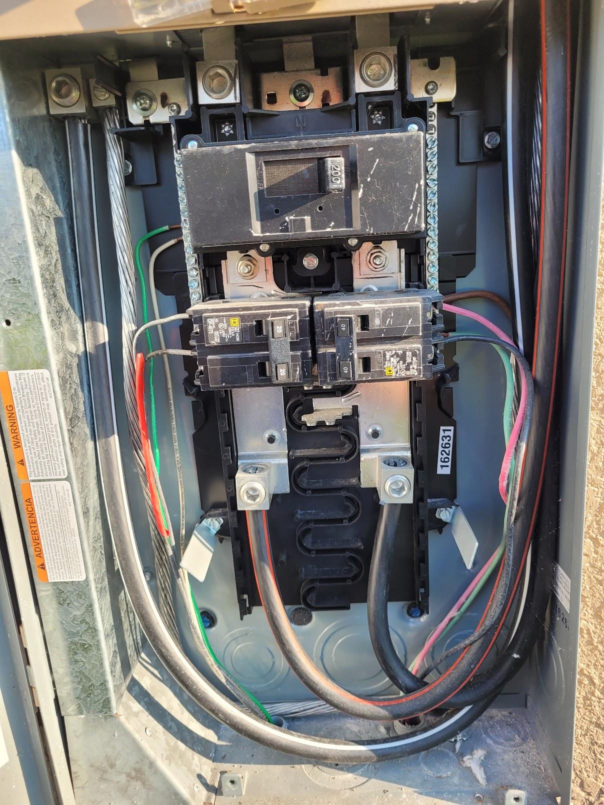
I see two approaches to monitoring this panel:
1 – Use 50 amp CTs to monitor the two branch circuits, use the optional flexible 200 amp CTs around the bus bars in the very top of the panel, and another Vue 2 in the subpanel, connecting it in the app as a sub of this panel. I expect the flexible CTs will fit in the space available. How thick are they?
2 – Use 50 amp CTs monitoring the Irrigation and A/C circuits with another Vue 2 in the 200 amp subpanel, and have the Emporia app sum these two branch circuits with the 200 amp CTs from the subpanel to get my full mains draw. Can it do that?
Thank you.
-
yyzguy
MemberI’m pretty sure you’ll need to use option 1. Emporia has suggested they intend to introduce “nested vues” in the future but haven’t done so.
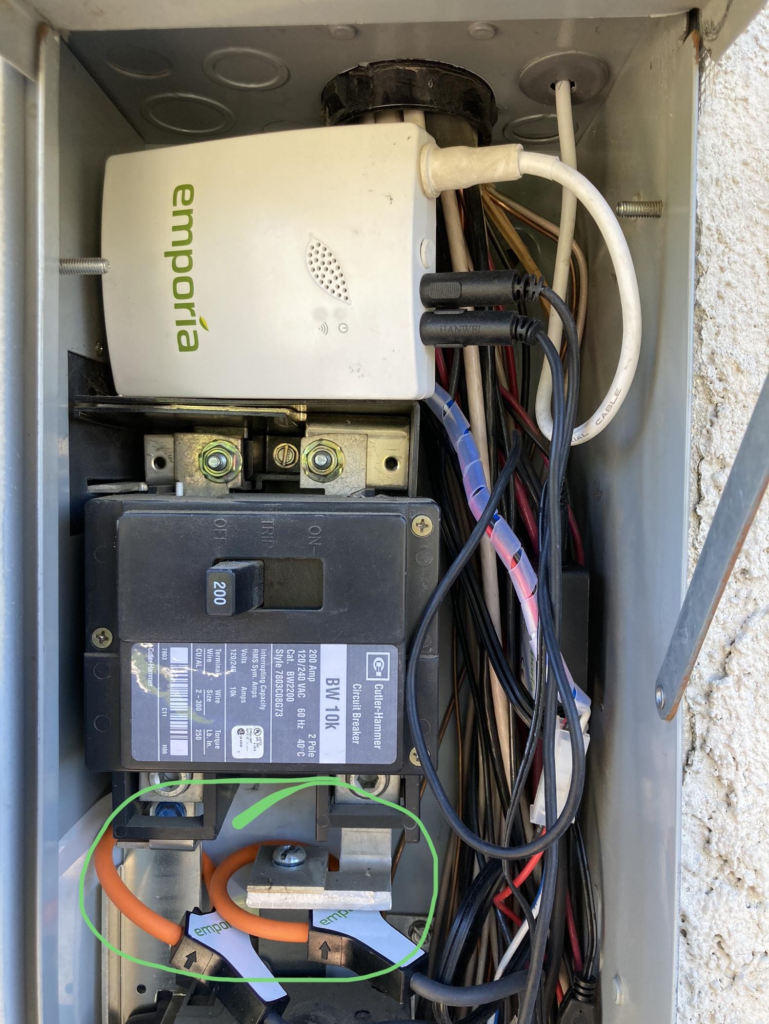
You shouldn’t have any problems using the flexible CT clamps. My busbars look similar to yours and fit easily. However, unless you can turn off the power from the meter, please don’t install them above the breaker….those are hot! Install them below the breaker, with the breaker in the off position.
-
This reply was modified 10 months, 1 week ago by
yyzguy.
-
This reply was modified 10 months, 1 week ago by
-
Member
Thank you for the reply.
Unfortunately, the busbars downstream of the service disconnect breaker are flush with their plastic mounting hardware, so I don’t think I’ll be able to get the flexible CTs around them without ending up below where the branch circuit breakers mount which leaves me with the nesting problem of option 2.
I have found dimensioned drawings for the flexible CTs, and thin clamp CTs, in the online store and will measure available spaces. I might be able to shut down the disconnect and be able to work the flexible CTs through the gaps and around the bus bars just above where the branch circuit breakers are now (pulling those to give more clearance while I work) but just rough eyeballing it those spaces look too small.
I appreciate your caution re the top bars, which may be my only choice to directly monitor the full load. Those most definitely are always live unless the power company gets paid to come out for a connect/reconnect visit. If I go that route I will likely do it live, I am not a novice in this regard. I routinely work around exposed 480v busbars in industrial three phase motor control cabinets and would not even consider attempting this without the guidance and support of a licensed professional electrician with whom I work.
-
This reply was modified 10 months, 1 week ago by
billmi.
-
This reply was modified 10 months, 1 week ago by
-
emporiacs
Emporia StaffHi,
There are various ways to solve for this it and will be best if you contact our support team directly so we can walk through the options.
info@emporiaenergy.com
844-EMPORIA (367-6742)Flexible sensors will be needed to monitor the main.
The 50A sensors and 2.5mm (side) ports will report accurately with high resolution between 0.04A – 75A (5W – 9000W). When you go below 0.04A, the readings will show ~0W. Although rated for 50A, you can use the CTs on breakers up to their 75A saturation point with a caveat. Up to 50A, they are linear — where the change in monitored current is equal to the change in sensed signal. Above 50A the linearity degrades until it reaches 75A, where the CT becomes “saturated” and the change in monitored current results in no change in the sensed signal. As you exceed 75A, the sensors and ports will reach saturation and will not report anything higher. Going above 75A does not pose any risk of damage to the device or sensors.
-
-
AuthorPosts
- You must be logged in to reply to this topic.