Emporia Energy Community › Support Center › Hardware and Installation › Measuring a 3rd leg, plus US 240v split-phase
- This topic has 3 replies, 3 voices, and was last updated 1 year, 5 months ago by
Emporia Support.
-
AuthorPosts
-
-
daklein
MemberI have set up the Vue2 in my main house panel, US 240V split phase, and it works well, set up per the instructions. It’s quite a fun toy!! (2 200A CTs on the feed to the panel, red & black 120v from those legs. The blue and white are both connected to neutral).

That main panel is served by an off-grid battery & solar setup, and there is a grid fed panel right next to it with several loads that are still on-grid. I’d like to monitor one or two loads from that grid panel, and those circuits pass through some common conduit so the CTs are easy to reach. One load is a 3800w water heater element. While the grid and off-grid panels all share the same neutral, and neutral-ground bond out in the main grid panel connection to the house outside, and they both are 60Hz nominally, they don’t stay syncronized. A 50A CT on the grid powered 3800w water heater circuit looks like the following, as the L1,L2 voltages and L1,L2 main CTs that the Vue sees in the off-grid panel, go in and out of phase with the grid.
What would happen if I hook up the blue voltage sense wire to the grid panel L1, leave the white on the neutral that’s common between both panels? That won’t hurt the Vue device, it’s measuring voltages to neutral? What if I add a third 200A CT on the grid panel main L1, to the C port on the Vue? How are the 50A load CTs mapped to the L1, L2 (L3?) voltages and main 200A CTs? I’m sure the app summary total will be goofy with this non-standard setup, but that’s ok, I’d like to just see what the individual load is by itself.
Any ideas or advice welcome, Thanks!
-
Ampster
MemberI had a similar situation with a different device than an Emporia. I never did find a solution except to have them all synced to the same 60 HZ signal. You could give it a try. I think the third port is for three phase but with three phase the assumption is they are all in sync but just 120 degrees out of phase, not a totally different frequency. The differences you are seeing may be only 0.1 of a Hz but enough to give you that cycled output.
-
This reply was modified 1 year, 5 months ago by
Ampster.
-
This reply was modified 1 year, 5 months ago by
-
Member
Yes, the difference in frequency is pretty small, but it would be moving in and out of phase. This plot is from the inverters, which also see the grid.
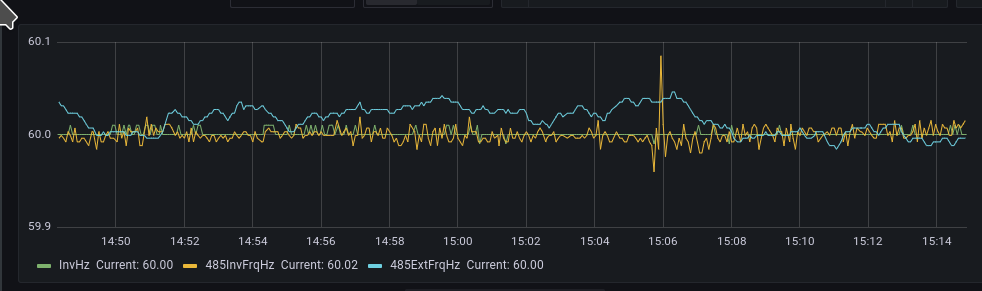
The Emporia plot looks like the current is measured not as just an average over cycles, but fast enough that it has phase information in it. When it’s multiplied by (which one of?) the line voltage signals, they go out of sync and give the beating watts signal. If each CT input could have a selectable line voltage with which to use, then maybe it would work.
-
Emporia Support
Emporia StaffYou can use the 200A CTs to monitor circuits other than your mains, however, keep these things in mind:
- The usage for all 200A sensors is combined in the App and cannot be broken out individually
- We calculate the Balance by subtracting the sum total of all of the circuits from the mains. Mains – Circuit Totals = Balance. Placing the mains on anything but your total load will drastically impact this reading.
If you would like to measure loads on the Grid panel I would recommend using a second Gen 2 Vue.
-
-
AuthorPosts
- You must be logged in to reply to this topic.