Forum Replies Created
-
AuthorPosts
-
Alan_B
MemberFebruary 4, 2022 at 10:56 am in reply to: UK Install – No space in consumer unit for probes – What to do? #8315 Report AbuseMemberI feel your pain Mike!
I eventually managed to fit five sensors inside my small consumer unit, and can just about get the cover back on! There was no room for the 200A sensor, nor for the monitor unit and all the excess sensor cable lengths. I therefore designed and 3D printed my own mount for the monitor – please see my post here for further details and photos.
As you’ll see from that post, I attached the 200A sensor to the live cable from the meter, and used a 2m 3.5mm mono jack extension cable to connect it to the monitor.
I hope this helps!
Alan
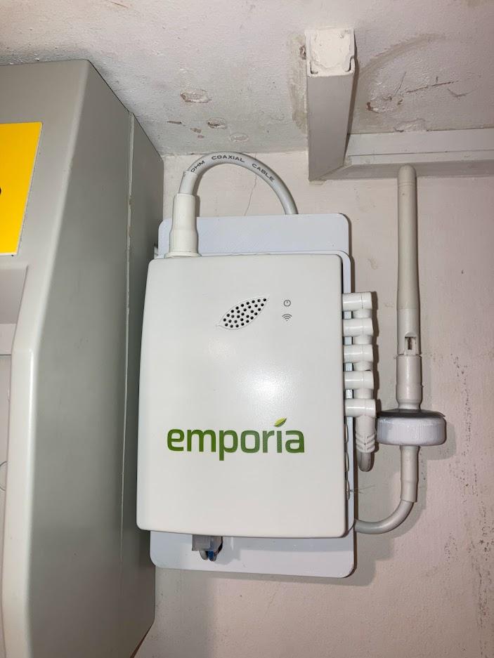
MemberI’m in the UK and have just installed my Vue monitor. Houses over here tend to have very small consumer units / electrical panels, so there was barely enough room to install the sensors. I therefore needed to site the monitor externally, and needed a mount to hold it and the excess sensor cable lengths. I therefore fired up my CAD package and designed a mount, which I then 3D printed:
The 50A sensor cables exit the main panel through cutouts at the top right, and the mount has a hollow base to accommodate the excess cable lengths:
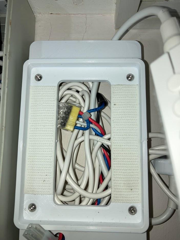
There was no room in the main panel for the 200A sensor, so that is instead fitted to the live cable from the electricity meter, and is connected to the monitor via a 2 metre screened 3.5mm mono jack extension cable (not shown in the photos as it’s only just arrived!). Domestic systems here are single phase, so I joined the white, blue and red wires together with a 4-way push-fit connector to an output combined neutral wire. This and the black wire then enter the main panel and are connected to an RCD breaker.
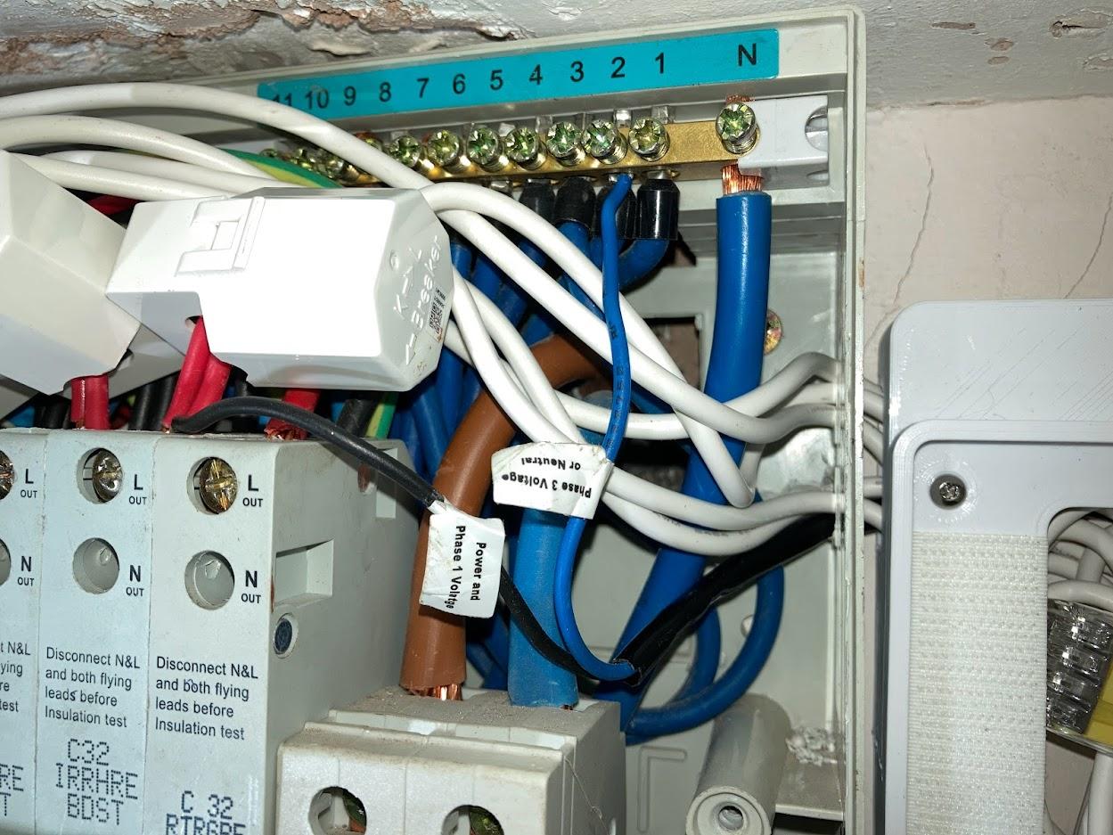
At first I ran the live wire to the L Out terminal on the breaker, and the neutral wire to the neutral bus bar. However, this caused the RCD to trip every time I turned the power on. Having then researched how RCDs work (!), I instead connected the neutral wire to the N Out terminal on the breaker, thus removing the current flow imbalance.
Strictly speaking the exposed power wires to the monitor should be in trunking, but they’re very short, so will do for now. I’ll modify the mount design to include a small removable cover in due course.
The monitor is secured to the mount by Velcro, so it is easily removable if required.
If my mount is of interest to others, I’m planning to post the STL files for it on Thingiverse.
Alan
PS: I’m a keen DIYer, not a qualified electrician. It’s a long time since the panel was inspected, so I plan to get an electrician in to check my work and perform a safety inspection.
-
AuthorPosts