Forum Replies Created
-
AuthorPosts
-
Lynoise
MemberI have seen something similar to this as well. It is easily reproducible by simply unplugging a CT sensor while it is measuring current. It continues to show a load (less than what it was measuring) for a little while. I will play around with this more tomorrow but that is what I recall it doing.
MemberThanks for the reply.
Is your setup similar to mine with the all in one unit so measuring the input is not possible via measuring a “solar breaker”? The way I depicted using 2 sensors per 120v line above does work. Like I said it is not perfect at it sees idle current (load) as solar generation, but it is so low that it doesn’t really matter to me. I am curious if others have done something similar or if there is another way to measure solar/battery usage with this type of system.
I have been running it for a full day now and it works just as expected. I have actually noted that the idle current ends up canceling itself out to some degree because while running on solar/battery the idle current (load) is still there so when solar is generating it is deducted from my generation KWH but while not on solar it is added as generation KWH, so its almost a wash! Just makes the historical charts off 100 or so watts in either direction.
MemberSo I tested the sensors in series as described above and it works as expected. I verified the measurements with known loads and solar (battery) inverter input.
The only issue is that when I am running with no solar/battery inverter input the CTs see a difference which is the power to simply run the Hybrid device (25-150 watts) and because the CTs are not measured directionally it gets measured as input from solar even though it is a load. I have seen other threads where folks would like to utilize their “solar” circuit as both a source and a load depending on circumstances.
Does the Vue and the CTs even have the appropriate hardware to determine the direction of power flow?
This setup as I have designed above is “good enough” for me at the moment but am always looking to improve things.
March 27, 2021 at 3:20 am in reply to: Using colors to display circuit “channels” for more data rich graphs #7212 Report AbuseMemberYes please.
I honestly assumed the graph would allow this (multi select when selecting the circuit). I spent some time taping around thinking I was just missing it.
Please please please add this, as well as pinch to zoom 🙂
MemberYes and you likely should if you want to measure the power usage of both circuits.
It will accurately measure both circuits together.
MemberEven more thinking (last one for tonight 🙂 )
Could I use 2 sensors one on each wire I want to “add” together (1 backwards so really difference) and wire the sensors together in series. They are actually just creating a voltage that is being measured right? So as long as I connect them in the correct “polarity” they should “add” together as expected? (as depicted below in the orange box).
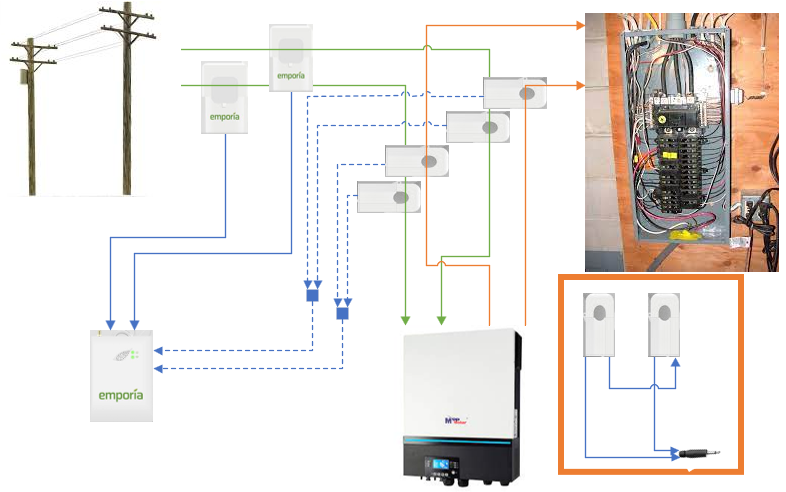
This assumes the AC running in each line is in phase with the other it is being differenced with but I think that is safe to assume (I can check as well).
-
This reply was modified 3 years, 1 month ago by
Lynoise. Reason: words
MemberThinking about this now, I am wondering if I could do something like this:
If the current coming from the grid into the inverter is measured along with the current coming out (but one is backwards of the other) then the net difference would be measured. That result would be the power being produced by the inverter (batteries and solar). If I take that and input it as a circuit and set that circuit as the solar input, would that function as expected? The main sensors would still be placed on the grid power lines coming in.
When the inverter is providing no power (dead batteries and no solar) then all power is from grid, mains sensors would measure that as input, and then the mains measured along with the output to my panel (backwards) would measure 0 (zero) because they are the same so the circuit would read 0 solar input.
It might be interesting to get the 2 wires within a single single sensor (how much are those flexible sensors? Can they be used as circuit sensors or just the mains?)
I might wire something up to just test this out. Any thoughts from the community?
-
This reply was modified 3 years, 1 month ago by
-
AuthorPosts