Forum Replies Created
-
AuthorPosts
-
OneMan
Member@mukwonago, I found this in the Gen 2 FAQ. Says 5 watt min reading, but I have a monitored circuit that draws just 3 watts in standby and my Gen 2 Vue reports this very accurately.
Our sensors have physical limitations. Each 200A sensor is accurate with high resolution between 0.04A – 250A (5W – 30kW @ 120V). And each 50A sensor is accurate with high resolution between 0.04A – 63A (5W – 7500W). When you go below those ranges, the sensors will report about 5W of noise. However, when in range, the sensors can resolve differences as low as a handful of watts. The app filters out this noise, so you’ll see no load when the sensors are below the threshold of 5 watts for either the 50A sensors and 200A sensors. However, if you download the raw data, you will see the reported noise – giving a slight discrepancy between the app and the raw data.
November 19, 2020 at 5:15 am in reply to: Installation with two wires per phase for mains? #6584 Report AbuseOneMan
Member@ razzfazz, you didn’t say that the 200a sensor you have couldn’t be placed over both wires of a phase, but if it can, that is the most straightforward solution. It will accurately report the current flowing through both wires, so the multiplier would be 1.
And as Adam confirmed, the multiplier of 2 and the sensor on only one wire of each phase should also be as good as gold. The common condition of the current in one wire not equaling the current in the other wire of equal size and condition is a bad connection which is a dangerous thing that creates excess heat and equipment failure at a minimum.
OneMan
MemberWhile we wait for the Emporia data services to be improved to be able to combine multiple Vues into one logical presentation in the app, here’s a couple solutions. And if you don’t need more than 16 branch circuits of monitoring for the entire home, then one Vue would always be better than two in my opinion.
I’ve learned from Emporia that the Vue understands current sensor signals equal to 370 amps max, and that is a lot for even a 400 amp service so a single Vue can reasonably handle a 400 amp service.
If the wires feeding the separate 200a main breakers are right next to each other at some point and accessible, you can put a single CT (current transformer aka current sensor) around both wires of each of the hot legs, one CT on two L1 wires and ditto for L2). The standard CT is probably too small in diameter but the rope CT should be big enough.
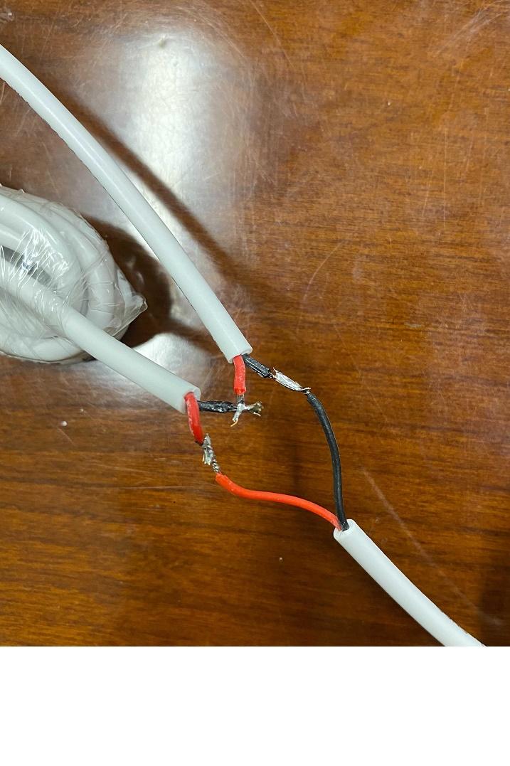
BUT, if the two wires are not accessible where close together (like behind the meter) or the two together are too big for the CT hole, then the other solution is to wire two CTs in series with only one jack on the end. Here’s the steps to do that:
Get 4 CTs that will fit around your main conductors. (You can order an extra pair on the website, rope CTs are larger in diameter and smaller in profile and easier to get into tight spaces.)
Take 2 of the CTs
On CT1, you cut off the last couple inches and the jack.
On CT2, you remove a couple inches of the outer insulation a few inches away from the jack. (If your arrangement warrants making the connection more than a few inches from the jack, that is perfectly fine. For example, you are placing the Vue in one panel at the bottom a couple feet away from the main conductors.)
On CT2, you leave the red wire untouched but you cut the black wire and solder or wire nut it to the red wire of CT1.
Lastly you have two black wires unconnected so you solder or wire nut them together.
If you soldered, then heat shrink tubing covers your work nicely. Make sure that uninsulated soldered joints can’t touch each other, of course.
Now you have two main CTs, wired in series into one jack which plugs into the Vue’s A or B port like normal. And about seven feet or cable in between them. If you need a bit more (I have no idea how long before it becomes inaccurate), you could wire in an additional length of suitable two conductor wire.
Repeat the above with the other pair of CTs.
See the pic below (but don’t cut the red wire and have to resolder it too! 😉
I’ve also done this with two of the standard 3.5mm audio splitter adapters that I found at Walmart for $4 each. It’s no easier to modify t these into series, but it does leave the Vue CTs unaltered and seems more cool. This is the kind of product that a manufacturer could offer. The Vue jacks are TS (Tip, Sleeve) style and these splitters are TRS (Tip, Ring, Sleeve for stereo) style but it worked fine for me.
Remember that the pair of series CTs are placed on the same phase (one set is on the two wires of L1 and another series set on the two L2 wires). If one in the series is on one phase, and the other is on the other, they cancel each other out and yield inaccurate readings.
Hope this helps!

OneMan
MemberI have solar and day 1 with my Gen 2 Vue, I saw that the Main (and Balance) kWh data was whacked, so I decided to take off and reinstall my two Main CTs backwards and then everything looked right. I confirmed the accuracy by comparing the daily and hourly Vue kWh with what my utility gets from my smart meter and posts on their website daily.
Solar production varying with cloud cover and loads turning on and off can make this kind of problem difficult to troubleshoot, but it may be worth a shot to try the flipping workaround.
I tried to get an explanation from Support as to how putting the Main CTs on backwards (and Support confirmed this via photos I sent) could get me accurate data, and got none other than there were code fixes done weeks after I flipped the two 200a CTs, so couldn’t have been my problem.
Good luck!
October 12, 2020 at 8:14 pm in reply to: Showing balance even when monitoring every circuit #6463 Report AbuseOneMan
MemberSupport and Development, what is the fix for this? I guess it is unreasonable to expect the sensors (current transformers) and voltage and phase sensing to be 100% accurate when not even the utility meter does that.
Should we be tweaking our multipliers to get rid of a “Balance” when all circuits are monitored?
Or perhaps Emporia would entertain adding a Vue config checkbox something like:
All circuits are monitored. Hide Balance unless greater than 3% of Main.
And behind the scenes, it could evenly distribute the phantom balance between all the channels. And it would need to account for solar backfeed too.
OneMan
MemberThe LEDs in the Vue2 must be tiny, because in daylight they are not easily visible for me. If I get close at the tiny holes in the leaf, I see a bit of light, more than I see through the power pinhole. The audible sound during power up is helpful.
Can you not see your Vue2 in the app? Support can get you up and running.
September 22, 2020 at 5:04 am in reply to: Home screen displays my Vue in collapsed mode even after Smart Plug deleted #6416 Report AbuseOneMan
MemberAs of last week, my app was back to normal and showing my only Emporia device, my Vue, in expanded mode, so it looks like this problem I reported has been fixed for me, at least.
Support, can you confirm that there was a bug in the app, or in the service side code or data? And what was fixed? Or was just some service side flag/data for my account that a developer fixed by hand? Or ??
September 17, 2020 at 6:42 pm in reply to: graph drop down to change loads from the graph page #6390 Report AbuseOneMan
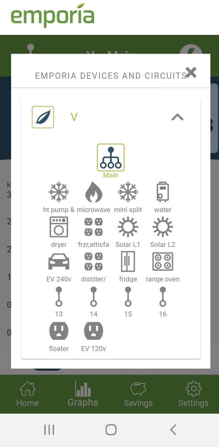
MemberHi @berfman, if you click the branch circuits symbol on the Graph screen (see pic)

It brings up a overlay window that shows all the Emporia Devices and Circuits (see pic)

And you can tap one and the app displays its graph! I think that is close to what you’re asking for, right?
I’m new to the Vue so I don’t know if this is a new feature coinciding with the release of the Gen 2 or predates it.
OneMan
MemberIt will be good to see ‘Balance’ brought into the fold. We also can’t create custom alerts/notifications for Balance as described here.
September 14, 2020 at 2:29 am in reply to: Ability to monitor the amperage for on both phases coming into the service #6379 Report AbuseOneMan
MemberEmporia has said that they are adding “combining” to the Home screen display and hopefully before 2020 is over. If anybody knows of any details on this, please post or repost!
Regarding @Jcdwing suggestion to show both phases – YES! And this is what I would expect to see – that the multiple phases combined into the Main line would be viewable by doing something like tapping a down arrow on the right of the line and seeing an expanded view of the combined channels.
Energy Use in kW
Main 12.040 100% ^
A 6.140 51%
B 5.900 49%
This same thing would apply to any multi-pole circuit and should be done whether it has sensors on every pole or only one sensor and a “multiplier” as it is currently called (that needs some refinement also) and in such a case, it would look something like this:
Water Heater 4.200 100% ^
A (no sensor) 2.100 50%
B 2.100 50%
Note that the Vue system has detected and is reporting which phase/hot leg it has a sensor on – the same one that is plugged into the current sensor port labeled B and reporting that the other hot leg does have a sensor and the value is mathematically derived.
What do you think?
September 11, 2020 at 4:32 am in reply to: Relationship between multiplier / amps / watts #6377 Report AbuseOneMan
MemberGood catch, @kkl. Marty and Support, you didn’t say how you plan on addressing it, but let me suggest this as an alternative to the current multiplier on the Circuit config screen.
“Current sensor on only one pole of multi-pole circuit” checkbox
Then the Vue will use that declaration and the info it obtains from its black, red, blue wires to figure out the rest.
“Adjust amps for unsensed pole(s)” number box
Allowing a positive or negative number representing the amps difference the user has observed with an ammeter in the poles that are not being sensed.
I’d use this adjuster for my electric clothes dryer where the leg that runs the 120v motor and half of the 240v heating element draws 5 amps more than the leg that doesn’t power the motor. If this could also be a percentage and not an absolute number, it would support many other scenarios.
The current multiplier does address both of these, but it is not enough info to show the correct amps.
What do you think?
OneMan
MemberSupport, wow this is really cool if the Gen 2 Vue can detect which phase a current sensor is on and match it with the voltage sensing input (black, red, blue wire) from the same phase. Can you point us to where it says that, please?
Voltage differs a bit for each hot leg and current typically differs substantially, so it is crucial that the Vue is doing the “maff” using the voltage and current reading from the same hot leg/phase.
OneMan
MemberThat’s good news. I wondered if the Vue’s white wire that was stuck in the screw hole in the photo was bonding (making contact) well enough.
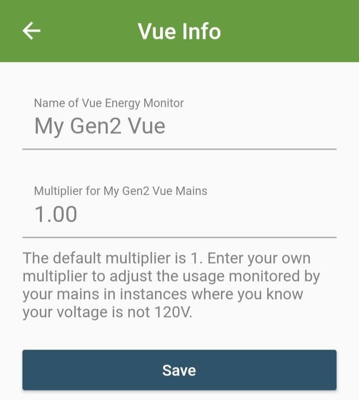
In regard to “we adjusted the multiplier to 1.83 for 220v”, I see how you came up with that number. It is 220 divided by 120 = 1.83333. The message you see when naming your Vue pictured in the screenshot below, I hope that it now pertains to the Gen 1 Vue only.

I don’t think you need to do that. Emporia has told me (I think) that the Gen 2 Vue can measure current, voltage (and phase relation) on up to three hot legs. Looks like you have the black wire on one hot leg of a breaker and the red wire on the other pole, right? So the Gen 2 Vue has the voltage and phase relation for the two hot legs. If all this is correct, there is no need to adjust the multiplier. Support, can you confirm or clarify?
Being totally unfamiliar with the grid in your part of the Philippines, knowing the following would be helpful:
You said you measured 237 volts. Was that between a Hot and Ground?
Looks like there are two hot legs coming into your breaker panel. What is the voltage between them? 475v?
OneMan
MemberThe Gen 2 Vue Installation Guide, page 25 says “100-240 VAC 50-60 Hz”.
Makes sense because power supplies for many devices have standardized on operating on anything between 100 VAC to 250 VAC and 50 to 60 Hz so as to be able to operate on the grid worldwide. Sounds like the Vue 2 should be able to handle the 230VAC 50Hz grid that most of the world has. And also the 100VAC 50 or 60 Hz of Japan.
The Gen 2 Installation Guide does not tell us which wires (black, red, white) are used for powering the Vue, but it should be from the black (connected to a hot leg) and the white (connected to the neutral).
I see a couple curious things in April’s breaker panel photo. It looks to be a two hot leg system which does exist in the Philippines and is 220/440VAC. If the Vue is powering itself from the red and black wire, well, it saw 440 to 480 volts and the magic smoke probably left it! The other possibility of the Vue not running is that the Vue’s white wire is stuck in a hole and may not be bonded well enough to get the 220V.
Semi-related tidbit is that the Gen 2 Vue adds measurement of the voltage of up to three hot legs, not just one hot leg like the Gen 1 and the assumption that the other legs were the same voltage. For the North American split phase 120/240VAC system, that means two hot legs with the black wire attached to one hot leg and the red wire to the other. And the VAC between those two wires will be 240ish.
Emporia Support, it sounds like the FAQ needs to be updated with the Gen 2 voltage info, maybe the Gen 2 Installation Guide for non-North American grids.
April, I hope this helps.
-
AuthorPosts
